| .................FREQUENTLY ASKED QUESTIONS |
| THIS PAGE ( FREQUENTLY ASKED QUESTIONS) IS MOST IMPORTANT TO MARTIN WING CUSTOMERS-PILOTS. THE QUESTIONS & ANSWERS WILL ADVANCE YOUR KNOWLEDGE ABOUT YOUR MARTIN WING AND ALLOW YOU TO GET THE ANSWERS TO MANY QUESTIONS YOU MIGHT HAVE. IT'S GOOD TO VISIT THIS PAGE PERIODICALLY TO READ ANY NEW QUESTIONS & ANSWERS THAT MIGHT ARISE. |
| Email us your Questions @ highmartinwing@gmail.com |
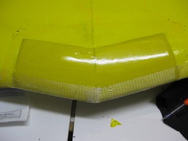
QUESTION/Statement From Alain Robillard:
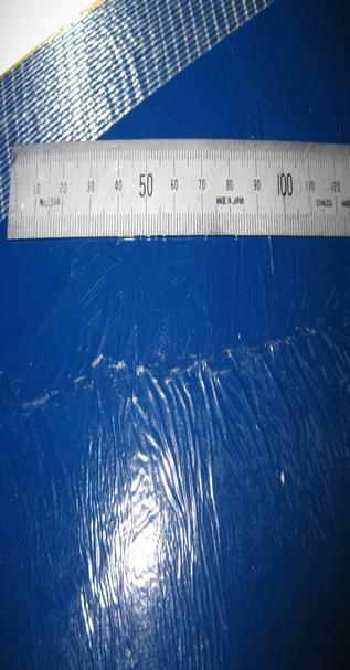
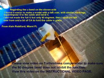
Regarding the U Bend Connector on the elevon horn, I found easier to make a model with a left over, with similar markings, superpose it to the cable and bend it.
I did not made the full U but only 90 degrees, then I used the left over horn and a bit of CA to hold the cable in place.
ANSWER: First: I like your idea about using the leftover part of the horn to make your bend. I'm worried that your 90 degree connector will interference in Turtle/Stress Compensator ( T/S C) function. The reason the connection is a U bend is so that it does not interfere in the function of the T/S C cutout. Please view the video below on the Function of the T/S C (on this page) ( https://www.youtube.com/watch?v=GLhLKLrPmxA) to make sure that your 90 degree connector does not inhibit the function. ( movement of the elevon to be able to flip up onto the upper surface as shown in the video without any interference from the control wire connection at the horn)
|
 |
| CLICK ON PICTURE TO ENLARGE |
|
|
? George, How frequently should I change my control wires and elevon hinges to attain the smooth quick control of my Martin.
ANSWER; Well, there is no given time because it depends on the amount of air time and ruff landings of the individual. No doubt that you should start every flying season (spring) with new control wires and hinges. Also, if your elevons have been broken/cracked and repaired I would recommend changing them at the same time. I change both my control wires, elevons and hinges about every 4 to 6 month and without question at the beginning of every flying season. NOTE: When you become proficient at flying your Martin if the wires/hinges become sloppy ( you don't have the same smooth/quick control as you did when they were new ) you will recognize this and that is the time for new hinges & wires. The more proficient you become the sooner you will recognize this. When you become a proficient pilot the Martin will no longer be a flying wing, the Martin will become an extension of "your self".
|
? Danny Chapman issue with his Martin!
" The Wing is standing up to the punishment I throw at it pretty well, though I think I need to fit new elevons. My only "issue" has been that the flex in the elevons, which allows them to withstand "rough" landings, means they become less and less effective at higher airspeeds. In fact, I was finding that if I put the wing into a dive (especially with the extra weight of a camera or ballast in higher winds), after a certain speed it wouldn't pull up! Since then I've reinforced the elevons with a strip of plywood (to stop them flexing), and also put a shim of 1/16" ply under the control horn so it has more authority. This does the job, but does mean they won't "flip" on crash landing. No problems so far, though.
ANSWER:
Danny thank you for the feedback on your Martin! Yes ... Most likely (depending on your flying) they will eventually brake along with striping your servos gears. PLEASE READ ON>>>>>>>>>> Yes,.....Besides the Turtle/stress compensator enabling some flex the stock elevons develop this issue after several months depending on environment, control wire being stressed and the tape hinge stretching. I change my hinges & control wires about every 4 to 6 months depending on air time. After experimenting with many airfoils the finished product the Martin Wing is a combination of the best airfoils to produce maximum performance with ease of flying which was key in it's development. Then came the controls. Before the turtle/stress compensators were incorporated into the design there was little to no flex. The prototype was flown this way for years but with the need of many repairs to the elevons,servos and wires. The problem was the design was striping servos, breaking wires & breaking elevons readily. After years & many hours of air time of experimenting with different control mechanisms, servos, control lines (stiff & flexible) what is stock now was the best of all combinations that I came up with still enabling excellent control of the wing. Also this combination servos/wires/connectors/ turtle-stress compensators turned out to be the longest lasting with the lowest maintenance which was of utmost importance for the customer. Let us know how you make out with your mod! Again thank you for the great video and your feedback. George
|
? Matt Doncaster UK ....
What are the dimensions of the receiver that will fit correctly in the Martin Wing Electronics cutout ?
HEIGHT MAXIMUM = 2 CM / 3/4 INCH ( NOTE: This is including crystal & connectors. )
WIDTH MAXIMUM = 3 CM / 1 1/8 INCH
LENGTH = All receivers meeting the above criteria will have acceptable lengths.
|
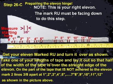
ON REPLACING THE HINGE OF YOUR ELEVON: ( after cutting the elevons tape ,with a razor, where the trailing edge meets the leading edge of the elevon ( the hinge bending point). NOTE: Before you replace the elevon hinge on the old elevon... If the elevons are damaged it's best to replace them now!
?) Ann Dunlap, George, the trailing edge (foam) at the hinge on one side, ripped off during the last time I replaced the hinge. I tried to tape the foam back in place.. but that didn't work very good.
First to prevent damage to the trailing edge when trying to remove tape it usually helps if you heat the tape up first "slightly" (not so hot as to melt the foam) with a hair dryer. It depends on how long the tape has been on and its condition. I heat it up slightly and then use another piece of tape to remove it pulling parallel to the trailing edge. What ever tape remains I scrape with a sharp razor cleaning it up the best I can without damaging the elevon. NOTE: If the elevons are damaged it is best to replace them now!
If some of the trailing edge foam comes off while doing this procedure you will need to glue it back in place the best you can. Then rap the trailing edge with a length of tape 1/2 " wide, 1/4 on the upper surface-1/4 on the lower surface piece of tape slightly longer than the elevon before applying your new hinge. This can be done on both sides when applying new hinges. NOTE: It is important that the area that you are repairing ( the length of the elevon) is straight. Use a ruler when applying the raped tape to your trailing edge before applying your elevon - elevon/hinge. This will ensure that your elevon has free travel.
|
A MUST READ FOR ALL MARTIN WING PILOTS
NOTE: ELEVON HINGE MODIFICATION *****
October 2014,
The hinge construction for the elevon has been modified from 5 panels to 12 panels. The additional panels increase the longevity and the flexibility of the hinge. The increase in panels will give you precision control for a greater period of time. This procedure is explained on the MARTIN WING ASSEMBLY PAGE under the DETAILED ASSEMBLY Steps 26 throw 27.
RU = Right upper surface
LU = Left upper surface
The under surface trailing edge, where the elevon is connected, has a 45% bevel to enable the elevon to be lowered by the wire control without resistance.
NOTE: You will still need to exchange your hinge, ( strip the old tape off and apply a new tape hinge) depending on your flying hours, about twice a year. Read the above entry on the helpful way to remove the old tape after cutting the elevons tape ,with a razor, where the trailing edge meets the leading edge of the elevon ( the hinge bending point).
|
 |
| NEW WAY>> 12 PANEL HINGE |
|
|
 |
| OLD WAY>>> 5 PANEL HINGE |
|
|
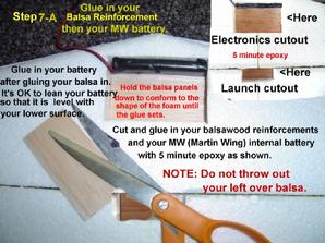
?) ABOUT GLUING IN YOUR BALSA REINFORCEMENTS WITH 5 MINUTE EPOXY:
Danny Chapman : Had some trouble getting the balsa to conform to the shape of the foam with out breaking when gluing them into the electronic box and the throw/launch hole.
1) A good way to get the correct size/fit when cutting your balsa reinforcement is first to cut a paper/cardboard pattern of both the electronic & throw/launch cutouts. The correct size/fit makes it easer. The reinforcement balsa panel should fit in snugly but not so snug that they need to be forced into place.
2)YOU CAN.... After getting the correct size/shape cutouts...( when you're ready to glue them in) Wet your balsa reinforcement cutouts with warm-hot water, wipe off the excess water. This will make them more flexible, so to conforming to the upper surface, and less likely to brake/crack when holding them in place while waiting for the glue to set.
P.S. No worries if the balsa cracks! As long as the balsa reinforcements are glued in the area will be strong enough to support their function.
NOTE: DO NOT USE GORILLA GLUE for this application, it will break through your upper surface.
|
 |
| CLICK TO ENLARGE |
|
|
Hi everyone! ( OCTOBER 6 2014) ! I have received many request for a shorter version of the Martin Wing Assembly from those who have built foam wings previously.
So here it is: A 28 STEP MARTIN WING ASSEMBLY! On the MARTIN WING ASSEMBLY PAGE.
For those of you that need further detail the DETAILED ASSEMBLY INSTRUCTIONS are on the lower page.
ALSO:
The DETAILED ASSEMBLY INSTRUCTIONS have been updated to show you what steps have already been done for you. Each Step that I have already finished for you is marked " DONE".
The only Step that was modified was STEP 26 , the buildingg of the hinge for the elevons. The # of hinge panels has been increased. The additional hinge panels increase the strength and longevity of the hinge which is paramount for superior control of pitch and roll ( controlling your Martin).
You will still need to exchange your hinge, ( strip the old one off and apply a new one) depending on your flying hours and crashes, about twice a year.
|
? George my Martin has to much dihedral. How do I remove it now that my Martin is already completely built.
OK, The three videos on the right will explain how to do this.
|
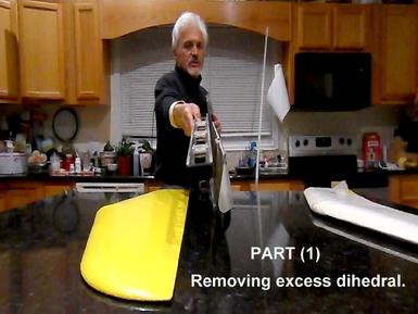 |
| George Ferris of Martin Wing instructional video:PART (1) 0f (3) Removing excessive dihedral​. |
|
|
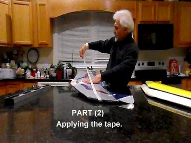 |
| George Ferris of Martin Wing Instructional video:PART (2) 0f (3) Removing excessive dihedral. |
|
|
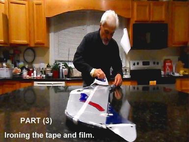 |
| George Ferris of Martin Wing instructional video:PART (3) 0f (3) Removing excessive dihedral. |
|
|
? George would you please explain what the Turtle Compensators are used for in a video.
OK, Video on the right!
|
 |
| INSTRUCTIONAL VIDEO |
|
|
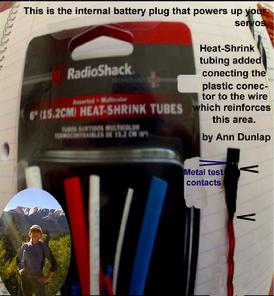
? How can I reinforce my internal battery connector that powers up my servos?
( Adding heat-shrink tubing)
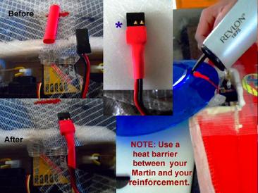
Ann Dunlap answers this question: I found that adding heat shrink tubing works great for strengthening the wire attached to the Martin Wing internal battery plastic connector. This is the connector that you plug into your receiver to power up your servos. This gives you a little handle to hold on to when you're plugging in and unplugging your internal battery. I no longer need to worry about stressing the wire or pulling the wires out of the plastic connector because of the added heat shrink material!
NOTE: Make sure when applying the Heat-Shrink you have a barrier between it and your glider. If not, the heat (temperature) that is used to apply the Heat Shrink , even when using a hair dryer, WILL MELT YOUR "FOAM" GLIDER!
Select a 1/4" DIA heat shrink tube. Cut a 1" to 1 1/2" length. Slip it over the plastic connector and pull it down 1/16" below the metal testers ( see picture *). Put a heat barrier, a plate will do, between the heat shrink-wire and the glider. This is a must! Then using your hair dryer shrink the tubing onto the plastic battery connector and the battery wire. Now you have a handle to hold onto when plugging and unplugging your battery.
I would like to thank Ann Dunlap for sharing the above with us. This reenforcement will be incorporated into the Martin Wing Assembly instructions.
|
|
|
|
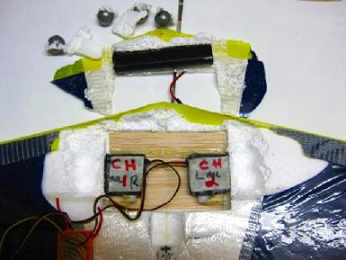
? George, I had a nose in landing and this is what happened. This photo was sent to me from this customer. I had never seen this happen before but it's things like this that we can all learn from. After studying the photo I explained , from what I could see, why this happened. After all this should be one of the strongest areas of anyone's Martin after assembly.
As you can see the battery broke away from the rest of the glider. It appears that after studying the photo the reason this happened is because of the gluing process. When Gluing the battery in it must be glued not only to the sides and the front of the foam it must also be glued solidly to the balsa base underneath and to the servos that are mounted afterwards. At this point in the build it's better to use more glue than needed than not enough. The added weight is not a factor because additional weight will be added when the wing is finished to set your CG. Steps 12A + 12B on the assembly page show a finished photo of the amount of Gorilla glue that I use to reinforce this area making the battery, servos, along with the tape conform to one solid area which strengthens this area to be one of the strongest areas of your Martin. Also it's a advantage to put your CG weights in front of your battery which additionally strengthens the nose area , when glued in, and lessons the amount of weight needed to acquire the proper CG.
NOTE: Gorilla glue when dried has a flexible property to it unlike epoxy that has no flex and has a tendency to crack during hard landings. After initially using 5 minute epoxy to hold your battery then servos in place I highly recommend reinforcing this whole area with Gorilla glue.
We all thank you for making this mistake so we can learn the proper way of assembling this area. If it was my directions that caused you not to understand the proper possess I apologize. This gives me a chance to reinforce the importance of properly gluing everything together in this area which leads once again to the word reinforce, Thank you, George
|
|
 |
| Beautiful Repair |
|
|
?) Ann Dunlap, George. Hey, if I could only get a camera on my Martin...
Actually, you could tape your camera to the bottom of your Martin at your electronics location. I want to get a camera like yours soon. I think it will help with my future instructional videos and I plan on mounting it on the Martin also. If it's in aprotective case it should be fine, don't you think?
Best do some testing first.. says the test pilot in me. Get together with Mike and come up with something very close, or if you have scale the same weight. Also the same shape and size. The shape-size is more important than the weight being 'exact' because it will have the most effect on the aerodynamics. Take a few test flights with your mock camera mounted with "one" piece MW tape. This way you can adjust the mock camera forward and back to feel where the glider fly's best. ( always forward of the CG point) Start off at the rear of the electronics box.
Fly in different wind conditions to evaluate what conditions best suit your added parasitic drag ( camera ) if any.
(**Parasitic drag is drag caused by moving a solid object through a fluid medium**)
Also if you make your mock camera exterior out of your MW bed foam it will give you a good Idea of the kind of possible damage that your camera case needs to endure. Just glue some foam together shape it and fill the center with rocks.. whatever until the correct weight is achieved. Please film some of this if you decide to take on this assignment penny... penny... OOO pennymoney. If not... destroy this evidence.
|
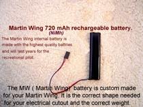
?)George, There are no markings on the MW rechargeable battery, is it NMHD or LiPO?
It's a 720 mAh NiMh 4 cell rechargeable battery. Charge it at any time. It is a quality battery and will last you for years. It has a minimum flying time of 4 hours fully charged.
|
|
?) George, I’ve ironed the solite using what I think is a moderate heat ( I can still briefly touch the iron surface with my hand ) but it hasn’t taken out all the wrinkles. Do I need to try it hotter?
| |
Rick, Looking at the picture you sent me the temperature of your iron looks perfect at this point.
Most, if not all, of these wrinkles will come out but don't worry about it until the Martin is completely finished. ( I couldn't tell from your picture if it was complete.)
There are different ways of removing the wrinkles I see .... 1) wet the area slightly then iron at the same temperature, 2)continue to go over the same area slowly until they are gone , some times taking a few minutes, 3) turn the temperature up slightly and go over the "whole wing".
NOTE: It's best to do the final ironing after the Martin is complete, not before. At this point iron the whole Martin on the setting, moderate heat, you have been using then as you're ironing turn the heat up "slightly" and keep ironing, the whole Martin again. DO NOT STOP MOVING THE IRON at the higher temperature as you again iron the whole Martin.
NOTE: as soon as you're done, don't forget to turn the iron temperature back to the previous setting otherwise you will most likely burn through the film the next time you iron. ( It's always good to iron the complete Martin including the tape after a day of flying before you put it on charge for the night.)
Note: There are areas, like near the carbon fiber spar where some wrinkles may not come out completely. Don't worry about this!
The most impotent thing when it comes to ironing is to iron the whole wing evenly, applying the heat over the whole surface top and bottom. Applying heat to one area only can result in uneven shrinkage of the film which will produce a negative result. It may do one or several things..... put a twist in the wing, change in the dihedral - anhedral, or reflex-washout in the wing. IT COMES DOWN TO THIS... it's better to have a few wrinkles, then to over shrink the film.
Looking forward to your New Zealand Pictures ...Great Martin flying to Ya!!
|
(?) George even though I read what the function of the turtle compensators were on the Frequently Asked Questions Page I didn't completely understand how they worked.
After flying my new Martin for several months and seeing them in action I sure do now!
What a great Idea.
The last Martin I bought from you, years ago, did not have this feature and because of that I striped servos, and broke many wires. I gave my old Martin to my son which still flies great. Also, I love the new U connectors. They are much better than the Z bends. The U bend doesn't cut into the control horns like the bear wire did and they eliminate the sloppyness in the controls .
My questions is, can I incorporate these new features in my sons Martin?
Yes,
After removing the control wires follow the instructions in Step13, Step16C, Steps 25B through 25G, to create the Turtle commentator cutouts.
Then connect your wires using the U connectors.. Steps 29B through 29E and 31C through 31-I. Please send some video or pictures of you flying together.
|
(?) What is the proper sequence to power on and off my Martin?
Turning on : Turn the radio on first, then plug your M/W battery into your receiver.
Turning off : Unplug your M/W internal battery from your receiver first, then turn your radio off.
|
(?) George, I'm installing my M/W internal battery. If I put the width straight up and down as it shows it won't be level with the lower surface and if I lean it, so it is, when I install the servos the cutouts for the control wire sleeves won't line up with the out side of the servo arms like instructed. What am I doing wrong?
Nothing wrong! ,
Tilt the battery so the top is even, or slightly below the lower surface
as your knowledge of building has told you to do.
It's tilted in the picture you just can't see it.
As far as getting the control sleeving cutouts correct .......... please take a look at
Steps 14A and 14 B and that will answer your line up question.
Are you Back...... read on.........
I may change the location of the sleeve cutout where it enters the electronics cutout but they will most likely need to be modified slightly because everyone tilts their battery in slightly different and with the combination of the battery and servo position it is almost impossible to get the entry of the sleeve cutout to line up just to the outside of the servo arm for each builder. This is why Steps 14A &14B show you how to modify 3" of the cutout so that your control wire sleeves end up in the correct position. Thanks for the question, keep them coming.
|
(?) What is the wing loading of the Martin?
At 3.3 square feet the loadings are:
Build weights have ranged from 8 to 13 ounces giving a range of wing loadings from 3 to 4 oz. per sq. ft”
|
|
|
My Martin has some dents in it after weeks of flying. How or can they be removed?
|
Yes all or most of them can be removed by ironing these areas. With some patience you should be able to get most , maybe all, of them out. Stay on top of the dented foam area moving your iron constantly. It may take a few minutes but the foam will eventually heat up enough causing it to expand, in-turn removing your dent, dents.
NOTE: It's good practices to iron your whole Martin, tape included, at the end of each flying day. This will keep the dents out and maintain your airfoil in top performance condition.
|
|
|
Can I use a different film other than SOlite?
|
SOlite Film has moderate shrinkage properties which is best for any foam wing. You will notice in the long version of the Assembly instructions that we express low heat when applying the film and that the final ironing is not done until the whole wing is completely built. This is to make sure that the upper and lower surface film is shrunk evenly. It's critical that the covering (film) does not change, warp, or twist the wing.
If you decide to use a different film you need to be extremely careful about its shrinking properties. If the film is a heavy film not only are you adding weight you risk the chance of over shrinking the film. This can create several problems. (1) A twist in the wing which will cause the wing to act like a propeller. (2) Change the amount of dihedral in the wing. (3) Change the plan form. (4) Change the reflex and other problems. Each one of these will lessen the performance and a combination of the above might render the wing unflyable. Unflyable, is that a word ? Well it is in the Hang Gliding world.
|
|
What is the Span? Weight (ready to fly)? Airfoil?
Question from: Albuquerque Soaring Association
Span: 49" ... Cord at center section 12"
Weight (ready to fly) : 9oz to 13oz the total weight depends on the builder, how much glue, tape, etc. is used.
The stock average is 11oz.
The airfoil is a custom Martin Wing airfoil ( patent pending).
|
|
|
|
|
Assembly Manuel Correction (These corrections are done as of 8/30/2013)
If you finished building your Martin before 8/30/2013 please refer to the NOTE below.
|
There is one step in particular that we need to modify the directions on and
we want to make sure you receive the correct information. In Step 14A-
long version, Step 9 short version, shows the control wire sleeve lining up
with your servo arm. We have found this to be a small problem. The
control wire will be restricted by the servo arm shaft when the control
stick is held at full corner.
The correction is to have the sleeve exit slightly to the outside of the servo arm not in line with the servo arm . This way when the control wire is connected to the servo arm by the U connector and full corner control stick is applied there will be no interference. The interference in the long run may strip the servo. I will be making this correction in the directions as soon as I finish new pictures and captions.
NOTE: If you finished building your Martin before 8/30/2013 , it's still an easy fix. Using a small screw driver break away the glue around the control wire sleeve enough so that you can move the sleeve slightly to the outside of the servo arm. Before gluing the sleeve into its new position rap the wire and the end of the sleeve with a piece of cloth. This will prevent any glue sticking to your wire or seeping into your sleeve. Do not use tape. If tape adhesive (any adhesive) comes in contact with your control wire it will restrict or stop the wire movement resulting in a bent or broken wire. 5 minute epoxy can be used for this correction. I apologize for the inconvenience.
If you have any questions feel free to call me at 727-2043932.
George Ferris
P.S. If you live in the Atlanta Georgia area call me and I will fix it for you.
|
|
|
I don't have any prior flying experience. How should I start?
|
This is great! Learning about the ocean of air we live in is exciting and rewarding. I remember back when I started. I was frustrated at first but as my knowledge grew I was elated at every step I took. I would Join your local RC club. Seek out those who are into glider soaring and they will teach you about wind speed, wind direction, ground speed ,etc that you will need to understand in order to fly your Martin. If you live in an area that has no RC club and can't locate anyone with pier flying experience call me 727-204 3932 and I will explain the steps and knowledge you need to get started.
Also, study the videos on the Video Page. There are some instructional videos and there will be more to come.
|
|
|
My elevons arrived with a bow in them. Do I need new ones?
|
No, when the Solite covering is applied and both sides are ironed evenly your elevons will lay flat.
|
|
|
What are Turtle-Stress Compensators?
|
Turtle compensators are the cutouts explained in Step 13 of the wing assembly along with a specific geometry setup for your control system. The purpose is to relieve stress-pressure on the control wires, servos and elevons which lengthen the life span of all three of these. Following the Martin Wing Assembly directions one full step at a time assures that your geometry will be set up correctly.
NOTE: A specific geometry is incorporated into your control system.
Understand that the height of your servo arms connections, the entry and height of your control wire connection, the height and location of your elevon horns along with the turtle compensator cutouts at the trailing edge are set up to conform to a specific geometry. Changing anything in the directions involving this geometry will disable the working geometry of the compensators resulting in their effectiveness or rendering the compensator geometry ineffective. In simple terms if you modify the controls you can expect a short life span of your control wires, servos and elevons.
At some point during one of your landings your glider will turtle, flip over backwards. When this happens your turtle compensators will enable your elevon or elevons to fold forward onto your upper surface. Other than in flight, if the control geometry detect stress-pressure ,like a ruff landing, the elevons will flip up onto your upper surface. This helps eliminate the elevon's from breaking, the wires from sharply bending-breaking and also prevents the servos from receiving reverse resistance ( pressure trying to reverse the gears) which eventually results in striping a gear in your servos.
In other words the turtle compensators ( stress-pressure relieves) acts like a modified week link in your control system to relieve any unwanted stress ( pressure) on your hardware. To get back into flying mode simply flip the elevon back up into flying position and your ready to go.
Also the Turtle compensators geometry comes in handy when transporting or shipping your Martin. With the electronics off reach into your electronics cutout and rotate your servo arms in towards your receiver and at the same time flip your elevons up and onto your upper surface. This will prevent your elevons from getting damaged during transport and eliminate any pressure on your control wires or servos. When your ready to fly again reverse the procedure,...electronics off. ALSO ( See Video "Function of the Turtle-stress Compensators" on the Instructional Video Page)
|
|
|
Where is the best place to add ballast on my Martin?
|
Assuming that your CG is correct ( 4 3/8" - 4 1/2" from the nose) it depends on conditions.
First, any ballast is always added from the CG forward but it has been found by experienced Martin pilots that ballast is always added between the tip of the nose back only to the center of the electronics cutout. WHY! because experience has shown this works best. I always advise pilots, when adding ballast, to just tape it on to the lower surface. This way you can easily remove it at the end of the flying day. There is no sense in making "ballast" permanent since each flying day calls for different ballast or no ballast at all.
I always carry lead plates that I have made from fishing sinker. Sinkers that I havee flattened out to a thin plate with a hammer. They range in size from a penny to a silver dollar. The lightest one is the weight of a penny the heaviest one I carry is two ounces. I using a strip of Martin Wing tape to apply the ballast to the lower surface.
Where you choose to tape this ballast on depends on your choice of feel. Lets say it a light wind day and I want to achieve a better glide. I would start out taping a penny size plate on the lower surface at the very nose of the Martin. I'll fly it a few times then move the weight back slightly and fly it again. Then I change the ballast, "guess I'll try a quarter size one" and fly it a few more times. When you become one with your Martin you will be able to feel the differences and find (the sweet spot) HA!!! Seriously!
I really get a kick out of Martin pilots when they finally achieve this level and they are always hooting about it " I'VE GOT THE SWEET SPOT gEORGE".
QUICK ANSWER:
If you were looking for the quick answer on adding ballast, again, assuming your CG is correct.......4 3/8" to 4 1/2" back from the tip of the nose............................
Adding Ballast:
Light wind: .......... Tape the ballast, penny??? Quarter??? to the nose on the lower surface.
High winds:...........Tape a flat 1oz, 2oz, 3oz weight ( depending on wind velocity) at the center of the electronics cutout , lower surface.
|
|
|
My iron got to hot and I burned a hole in my covering. What is the best way to repair it.
|
No problem! Get out your scrap SOlite and cut a round (no sharp corners piece) about 1/2" larger than your hole. Remove the clear covering and iron it on. Sharp corners have a tendency to pull up after time.
IMPORTANT: First, if you haven't, please read Step 21-C about testing your iron. When you're sure your iron is set at a temperature that will slowly take the wrinkles out of your SOlite not over shrink it, ( put a hole in it) , set it slightly lower, then tape the setting there so it can't move and leave it there. If you have already done all the previous then .......
..... Caution ..... When you first turn your iron on give it a couple of minutes to heat up evenly. Then, before using it run it across a dish cloth (towel) a couple of times. We have found that when irons initially are turned on, or if they have been sitting in the on position, that they will reach a temperature higher than its working setting. Rubbing the iron across a towel will release the stored up heat and return the iron to its setting.
|
|
|
KEEP THOSE QUESTIONS COMING
EMAIL QUESTION TO: HIGHMARTINWING@GMAIL.COM
| |
|
|